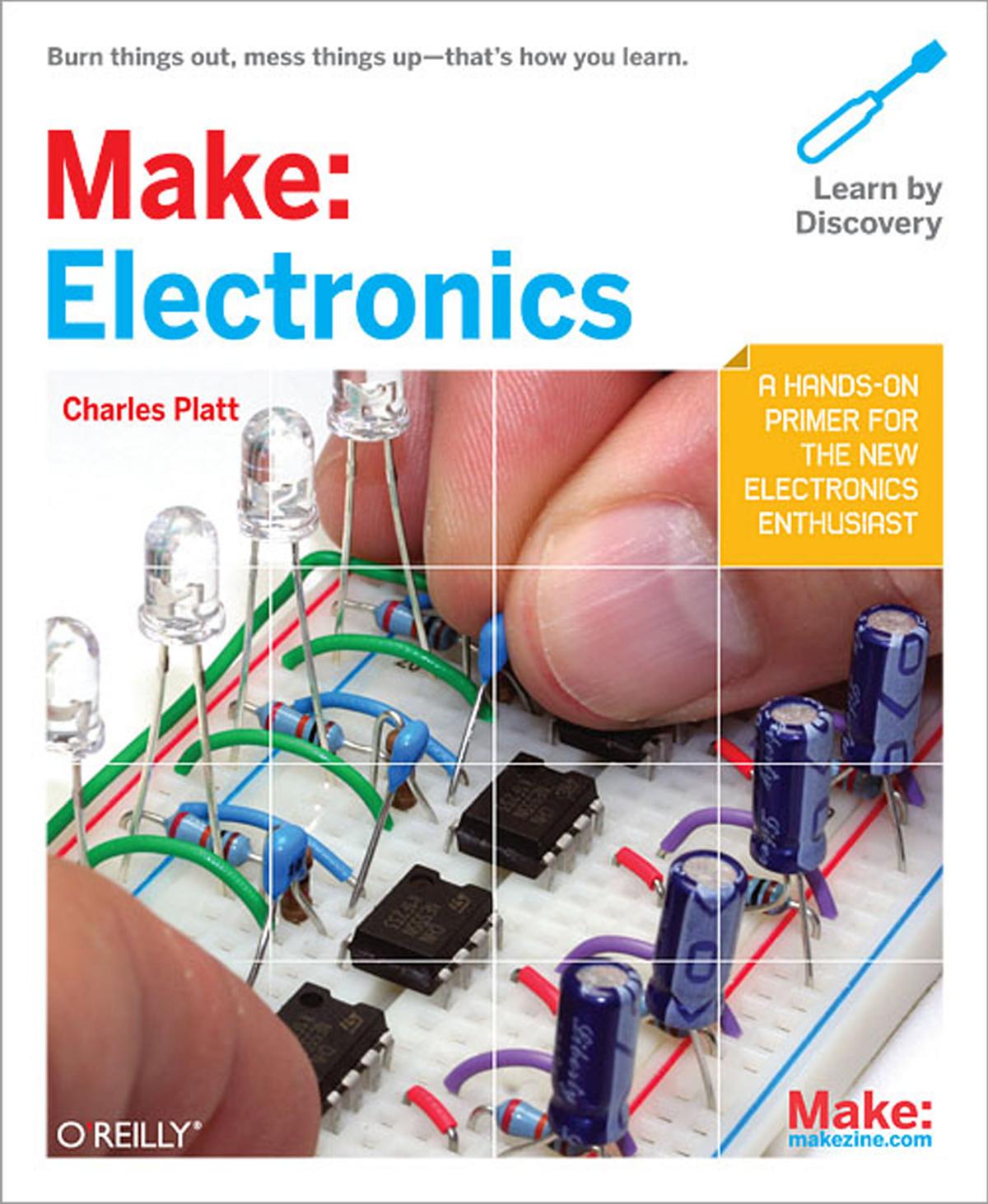
Make: Electronics by Charles Platt

Author:Charles Platt
Language: eng
Format: epub, mobi, pdf
Publisher: O'Reilly Media, Inc.
Published: 2011-06-15T16:00:00+00:00
Figure 4-21. These components should be added on the same breadboard below the components shown in Figure 4-14. Use the following values to test the 555 timer in its astable mode:
R1: 1K
R2: 10K
R3: 100Ω
C1: 0.047 µF ceramic or electrolytic
C2: 0.1 µF ceramic
IC2: 555 timer
Figure 4-22. This is the schematic version of the circuit shown in Figure 4-21. The component values are the same.
Theory
Inside the 555 timer: astable mode
Here’s what is happening now, illustrated in Figure 4-23. Initially, the flip-flop grounds C1 as before. But now the low voltage on the capacitor is connected from pin 7 to pin 2 through an external wire. The low voltage tells the chip to trigger itself. The flip-flop obediently flips to its “on” position and sends a positive pulse to the loudspeaker, while removing the negative voltage from pin 7.
Download
Make: Electronics by Charles Platt.mobi
Make: Electronics by Charles Platt.pdf
This site does not store any files on its server. We only index and link to content provided by other sites. Please contact the content providers to delete copyright contents if any and email us, we'll remove relevant links or contents immediately.
| Automotive | Engineering |
| Transportation |
Whiskies Galore by Ian Buxton(42003)
Introduction to Aircraft Design (Cambridge Aerospace Series) by John P. Fielding(33126)
Small Unmanned Fixed-wing Aircraft Design by Andrew J. Keane Andras Sobester James P. Scanlan & András Sóbester & James P. Scanlan(32797)
Craft Beer for the Homebrewer by Michael Agnew(18240)
Turbulence by E. J. Noyes(8042)
The Complete Stick Figure Physics Tutorials by Allen Sarah(7370)
The Thirst by Nesbo Jo(6938)
Kaplan MCAT General Chemistry Review by Kaplan(6931)
Bad Blood by John Carreyrou(6617)
Modelling of Convective Heat and Mass Transfer in Rotating Flows by Igor V. Shevchuk(6435)
Learning SQL by Alan Beaulieu(6287)
Weapons of Math Destruction by Cathy O'Neil(6273)
Man-made Catastrophes and Risk Information Concealment by Dmitry Chernov & Didier Sornette(6014)
Digital Minimalism by Cal Newport;(5755)
Life 3.0: Being Human in the Age of Artificial Intelligence by Tegmark Max(5552)
iGen by Jean M. Twenge(5412)
Secrets of Antigravity Propulsion: Tesla, UFOs, and Classified Aerospace Technology by Ph.D. Paul A. Laviolette(5371)
Design of Trajectory Optimization Approach for Space Maneuver Vehicle Skip Entry Problems by Runqi Chai & Al Savvaris & Antonios Tsourdos & Senchun Chai(5067)
Pale Blue Dot by Carl Sagan(5003)
